A heat exchanger transfers thermal energy between fluids while keeping them separated when the design requires it. The heat exchanger manufacturing process turns an approved thermal design into a finished unit through material selection, component forming, joining, assembly, and inspection. Exact steps depend on the exchanger type, working fluids, operating pressure, temperature, applicable codes, and required production volume.
What Is the Heat Exchanger Manufacturing Process?
The heat exchanger manufacturing process is the sequence of engineering and production activities used to build equipment that transfers heat safely and consistently. Common designs include plate, shell-and-tube, fin-and-tube, and brazed plate heat exchangers. Each design uses different components and joining methods, so no single factory workflow fits every product.
For example, a gasketed plate exchanger uses pressed plates, gaskets, and a frame. A shell-and-tube unit uses a shell, tube bundle, tube sheets, and channel components. A fin-and-tube exchanger adds fins to increase the available heat-transfer surface. Manufacturers therefore select a production route based on the design rather than following one universal recipe.
A well-defined heat exchanger manufacturing process also helps buyers compare supplier proposals using the same production and acceptance criteria.
What Are the Main Manufacturing Stages?
Most projects follow a controlled sequence: define the duty, approve the design, inspect materials, fabricate components, assemble the unit, test it, and prepare documentation. Some operations overlap, and special designs may add brazing, heat treatment, cleaning, or non-destructive examination.
1. Confirm requirements and complete the design
First, engineers confirm the process conditions and the customer’s operating requirements. They need fluid types, inlet and outlet temperatures, flow rates, design pressure, allowable pressure drop, installation limits, and cleaning requirements. They also check whether the fluids create corrosion, fouling, contamination, or safety concerns.
Next, engineers select a suitable exchanger type and calculate the required heat-transfer area. They assess flow arrangement, material compatibility, thermal performance, pressure loss, maintenance access, and expected service conditions. For shell-and-tube equipment, purchasers can use the TEMA standards as a reference for mechanical design and specification requirements. The project team must still confirm which code, edition, and contractual requirements apply.
Before production starts, the supplier should issue drawings, material specifications, connection details, and inspection requirements for approval. Clear design approval helps prevent dimensional conflicts and expensive changes later.
A documented heat exchanger manufacturing process should record these approvals before releasing parts to the shop floor.
2. Select and inspect raw materials
Material choice affects corrosion resistance, strength, thermal conductivity, weight, cost, and service life. Common options include stainless steel, carbon steel, copper, aluminum, titanium, and suitable gasket or brazing materials. The correct choice depends on fluid chemistry, temperature, pressure, and the applicable design rules.
Receiving inspection should verify material grades, dimensions, surface condition, and required certificates. When the specification calls for traceability, the manufacturer should link material records to the finished equipment. Teams should also segregate materials when mixing grades could create contamination or identification problems.
In a controlled heat exchanger manufacturing process, receiving checks prevent unsuitable stock from entering fabrication.
Do not select a material based on thermal conductivity alone. A highly conductive metal may still perform poorly if the process fluid causes corrosion or if the design cannot meet mechanical requirements.
3. Form and machine the components
Component fabrication varies by exchanger design. Plate heat exchangers usually require sheet preparation, pressing, trimming, and plate inspection. Shell-and-tube exchangers need shell rolling, tube-sheet machining, tube preparation, and the fabrication of channels and nozzles. Fin-and-tube units require tube cutting or bending and fin forming or attachment.
Manufacturers must control dimensions throughout these operations. Poor plate geometry can affect sealing and flow distribution. Incorrect tube lengths or bend radii can complicate assembly. Damaged surfaces, burrs, cracks, and out-of-tolerance parts can also create leaks or reduce service reliability.
The heat exchanger manufacturing process should define these checks before production starts, rather than after a defect appears.
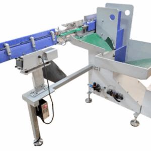
Production machinery should match the material, wall thickness, part geometry, tolerances, and output target. For copper tube coils, for example, a dedicated return-bending machine can form repeatable U-bends for condenser and evaporator coils. Fin-forming equipment supports the production of heat-transfer surfaces Plate Fin Press Forming Machine while cutting and end-forming machines prepare tubes for downstream assembly.
4. Join the parts using the correct method
Joining methods include welding, brazing, mechanical expansion, gasketed clamping, and other approved connections. The design and service conditions determine the suitable method. A gasketed plate exchanger relies on correct gasket placement and plate compression. A brazed plate exchanger bonds plates in a controlled furnace cycle. A shell-and-tube unit may use welded joints, expanded tube joints, or a combination.
Welding procedures, joint preparation, operator qualifications, and inspection criteria should follow the project specification and applicable code. Brazing requires compatible materials, clean surfaces, correct filler metal, and controlled heating. Mechanical expansion requires suitable tooling and dimensions to achieve the specified joint.
Manufacturers should not treat joining as a generic step. Incorrect heat input, contamination, poor fit-up, or inconsistent compression can cause leakage, distortion, or premature failure. The approved drawings and process instructions should define the acceptance criteria.
A robust heat exchanger manufacturing process records joining parameters and inspection results for each critical joint.
5. Clean and finish the assembly
Cleaning removes oil, chips, scale, flux residues, and other contaminants from manufacturing. The cleaning method must suit the material and the process fluid. Some products also require pickling, passivation, coating, drying, or other surface treatments.
This stage matters especially for food, pharmaceutical, high-purity, and sensitive process applications. Residues may contaminate the working fluid or interfere with later inspection. The manufacturer should document the cleaning method and confirm compatibility with the material and service requirements.
For brazed plate-fin exchangers, the manufacturer stacks fins, parting sheets, and side bars in the specified arrangement before vacuum brazing. Linde’s technical overview explains how these layers create separate flow passages and form a compact heat-transfer core. See its aluminium plate-fin heat exchanger guide for a design-specific example.
6. Inspect, test, and verify performance
Inspection confirms that the unit matches the approved drawings and acceptance requirements. Typical checks include dimensional inspection, visual examination, weld inspection, material traceability review, and selected non-destructive tests. The required methods depend on the exchanger design, risk, code, and purchase specification.
Pressure or leak testing checks the integrity of the relevant pressure boundary. The test medium, pressure, duration, isolation method, and acceptance criteria must come from the approved procedure and governing requirements. Pneumatic testing can store significant energy, so trained personnel must follow strict safety controls.
Performance testing may measure heat-transfer rate, flow, temperatures, and pressure drop. The ASME PTC 12.5 standard describes methods for testing single-phase heat exchangers and evaluating performance parameters. A pressure test alone does not prove that the exchanger meets its thermal duty.
Within the heat exchanger manufacturing process, testing must match the risks and performance requirements of the finished unit.
For plate heat exchangers, the manufacturer may inspect pressed plates for cracks, check gasket installation, verify tightening dimensions, and conduct pressure-resistance tests. HISAKA’s plate heat exchanger manufacturing overview illustrates these design-specific production and inspection steps.
7. Complete assembly, documentation, and delivery
After the unit passes the required checks, the team completes final assembly and verifies nozzles, supports, labels, accessories, and connections. The supplier should prepare the documents required by the contract. These may include approved drawings, material certificates, inspection reports, test records, operating instructions, and maintenance guidance.
Packaging should protect the equipment from impact, moisture, contamination, and corrosion during transport. Protective covers may be needed for openings and machined surfaces. The packing method should also reflect the shipping route and storage conditions.
How Do Manufacturing Processes Differ by Heat Exchanger Type?
The basic quality principles remain similar, but component production and joining methods vary by design. A well-planned heat exchanger manufacturing process links engineering requirements with shop-floor controls and final inspection.
Exchanger type | Typical production operations | Key checks |
Gasketed plate | Pressing, trimming, cleaning, gasket fitting, frame assembly | Plate condition, gasket position, compression dimensions, pressure integrity |
Brazed plate | Plate forming, stacking, furnace brazing, connection fitting | Brazing quality, cleanliness, leak integrity, thermal duty |
Shell-and-tube | Shell fabrication, tube-sheet machining, tube preparation, tube installation, joining | Dimensions, weld quality, tube joints, pressure integrity |
Fin-and-tube | Tube cutting and bending, fin forming, fin attachment, coil assembly | Tube geometry, fin spacing, joint quality, airflow or fluid-side performance |
Plate-fin | Layer preparation, stacking, controlled brazing, header and nozzle welding | Layer arrangement, braze integrity, leak testing, flow distribution |
These are typical workflows, not universal specifications. A supplier should confirm the route against the approved design and project requirements.
Which Quality Checks Matter Most?
Quality control should begin before fabrication and continue through final release. Relying only on a final test can allow avoidable defects to pass through several production stages.
- Material verification:Confirm grades, certificates, dimensions, and traceability where required.
- Dimensional checks:Verify critical features before parts move to the next operation.
- Joining inspection:Use the specified visual, non-destructive, or other checks for welds and joints.
- Pressure and leak tests:Follow the approved procedure and the applicable code.
- Performance verification:Measure thermal and hydraulic parameters when the contract requires them.
- Documentation review:Match test records and material documents to the equipment identification.
Inspection should reflect the consequences of failure. High-pressure, corrosive, hazardous, or critical-duty applications may require more extensive controls than lower-risk services. Never assume that one test method or standard applies to every exchanger.
What Common Manufacturing Mistakes Should You Avoid?
Many production problems begin with incomplete requirements or weak process control. The following mistakes deserve attention before placing an order.
- Starting production before drawing approval.Confirm dimensions, nozzles, connections, and maintenance clearances first.
- Choosing materials only by price.Review corrosion, temperature, pressure, and cleaning conditions.
- Ignoring tube or plate tolerances.Small dimensional errors can affect fit-up, sealing, and assembly.
- Using an unsuitable joining process.Match the method to the design, material, and operating conditions.
- Treating pressure testing as full performance proof.Verify thermal requirements separately when needed.
- Leaving acceptance criteria vague.Define the inspection scope, test method, and documentation before fabrication.
- Overlooking maintenance access.Consider cleaning, gasket replacement, tube inspection, and future repairs.
A clear specification helps the buyer and manufacturer resolve these questions before production begins.
These controls make the heat exchanger manufacturing process more predictable and easier to audit.
How Should You Choose a Manufacturing Machinery Supplier?
Choose equipment around the actual production process, not just the machine name or advertised output. Start by mapping the parts and operations that your factory needs to produce. Then compare the machine’s material range, part dimensions, repeatability, changeover needs, control system, tooling, safety features, and maintenance support.
Ask suppliers to confirm the required input materials, finished-part tolerances, cycle assumptions, and inspection method. Where practical, request a sample run or a documented acceptance test using representative parts. Also clarify installation, operator training, spare parts, warranty scope, and service arrangements.
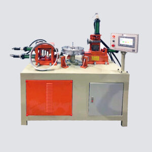
New Donor Machinery’s official website lists equipment related to tube processing and heat-transfer manufacturing, including a heat exchanger U-shape copper tube return bending machine Heat Exchanger U Shape Copper Tube Return Bending Machine . This type of equipment supports the tube-bending stage for relevant coil designs; it does not replace exchanger engineering, assembly, or final testing. Review the company’s official website and confirm the exact machine specification against your own production requirements.
When evaluating a supplier, distinguish between a machine builder and a complete heat exchanger manufacturer. A machinery supplier may provide equipment for selected production steps, while the buyer remains responsible for process integration, product design, and final quality unless the contract states otherwise.
Where Is the Heat Exchanger Manufacturing Process Used?
The process supports equipment for HVAC and refrigeration, industrial cooling, energy systems, chemical processing, food and beverage production, and many other thermal applications. However, each sector has different cleanliness, material, pressure, temperature, and regulatory requirements.
For example, a refrigeration coil may require accurate copper tube bending and fin assembly. A chemical process exchanger may require careful corrosion review and documented pressure-boundary inspection. A hygienic application may add stringent cleaning and surface-finish requirements. These differences should shape the design and production plan from the start.
Frequently Asked Questions
l How long does heat exchanger manufacturing take?
Lead time depends on the design, material availability, production workload, testing requirements, and approval process. A standard product may follow a different schedule from a custom or code-regulated unit. Ask the supplier for a project-specific schedule with design, fabrication, inspection, and delivery milestones.
l What materials do manufacturers use for heat exchangers?
Common materials include stainless steel, carbon steel, copper, aluminum, and titanium. Manufacturers choose materials according to fluid compatibility, pressure, temperature, corrosion risk, thermal requirements, and applicable codes. Gaskets and brazing alloys also need to suit the service conditions.
l Is welding required for every heat exchanger?
No. Some designs use welding, while others rely on brazing, gaskets, mechanical expansion, or combinations of joining methods. The approved design determines the suitable process and inspection requirements.
l Why does a heat exchanger need pressure testing?
Pressure testing helps verify the integrity of the pressure boundary under the specified test conditions. It does not automatically confirm thermal performance, fouling resistance, or long-term service life. The project specification should define all required tests.
l What equipment supports heat exchanger production?
Depending on the design, production may require cutting machines, tube benders, presses, fin-forming equipment, welding systems, brazing furnaces, cleaning equipment, assembly tools, and inspection instruments. Buyers should select equipment based on the actual parts, tolerances, materials, and production volume.
l What should buyers provide when requesting a quotation?
Provide the exchanger type, drawings, materials, tube or plate dimensions, required output, target tolerances, utilities, control preferences, safety requirements, and expected testing criteria. If the design is not final, explain which details remain open so the supplier can identify assumptions clearly.
l Does one manufacturing process suit every heat exchanger?
No. The heat exchanger manufacturing process varies with construction, materials, working fluids, pressure, temperature, and applicable requirements. Use a design-specific process plan and verify each critical stage against the approved documentation.
Conclusion
The heat exchanger manufacturing process starts with a clear thermal and mechanical specification. Manufacturers then control materials, forming, joining, cleaning, assembly, inspection, and documentation according to the exchanger design. Buyers should confirm the applicable standards and acceptance criteria before production begins.
For machinery projects, map each production step and select equipment that meets the required geometry, repeatability, and output. New Donor Machinery provides machinery for selected tube-processing and heat-transfer manufacturing operations. Visit bangwinmachine.com to review the available equipment, then confirm technical fit, tooling, testing, and service details with the supplier.
For related company information, you can also visit Bangwin Gas Cylinder. This link is a company-related resource, not a technical standard for heat exchanger manufacturing.